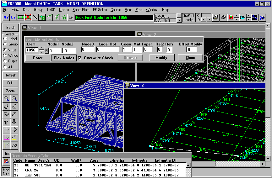
FS2000 Windows Graphical Interface
The multiple windows can be used to show different areas of the model.
For result case interrogation, multiple windows can show different cases and/or different areas.

Types of View
This view shows multiple windows and
the type of displays used for beam type elements.
For beam or pipe elements three types of graphic representations are
available.
Wire Line Represented by lines
using symbols for features such as offsets, releases etc.
Ghost View Same as Wire Line
but also includes the true outline shape of the beam.
Solid View Solid virtual view
with hidden line removal
For finite elements either Wire Line or Solid Views can be used.
Interactive Environment
FS2000 is a Fully graphical
interactive system.
All model definition and modification tasks can be done by
graphical/interactive means.
Minimal Keyboard Entry - Numerical
keyboard entry is minimised by:
Using relative entity definition to physically build up the
model
i.e. copying existing nodes & elements or by relative node
definition
Using geometric and material property libraries
Using the Parametric Frame Generator for standard configurations
ie portals, trusses, towers etc.
Using the various frame gen'n and mesh gen'n routines
Visual QA
Nodes and elements can be queried by
mouse selection.
Node co-ordinates and distances between nodes are shown.
Elements can be labelled with their material and geometric names.
Selective Views - e.g. Step through element properties (single
button click)
Solid views show a true physical representation of the model.
Virtually all definition data can be plotted.
Views can be dimensioned.
Permanent Visual QA - Hard Copies
Any FS2000 Window Viewport can be
saved at any time.
Saved views are dynamic - they always change to reflect the current
model status.
Saved views can show definition data or results data.
Views can be opened and printed at any time.
